ValuPoint Application Example - 4-20mA Output Connected to External BACnet Device
Our customer had the following requirement: Read a value from another BACnet MS/TP device, and produce a 4-20mA signal proportional to a certain range of the value read. The ValuPoint VP4-2330 is capable of doing this with just minor programming.
An object in the ValuPoint can only be mapped to one function at a time, either physical I/O or mapping to an external BACnet MS/TP device. When mapped to an external BACnet device, the ValuPoint will poll that device periodically and store the data received in its own local object. The same mapped object cannot also interface with local physical I/O, so two objects are needed – one for mapping to the other BACnet device and one for interfacing to the physical I/O.
Linking the two objects so that data from the remote BACnet device effectively controls the analog output is a very simple control algorithm, but is still technically "control” because output is being autonomously manipulated based on external data. Some scaling is necessary, but object configuration in ValuPoint already provides for built-in scaling. Therefore, assuming the scaling is configured, the control program simply needs to copy data from the input object to the output object.
Mapping an AV object to read an AI from another MS/TP device would look like this using the ValuPoint configuration tool:
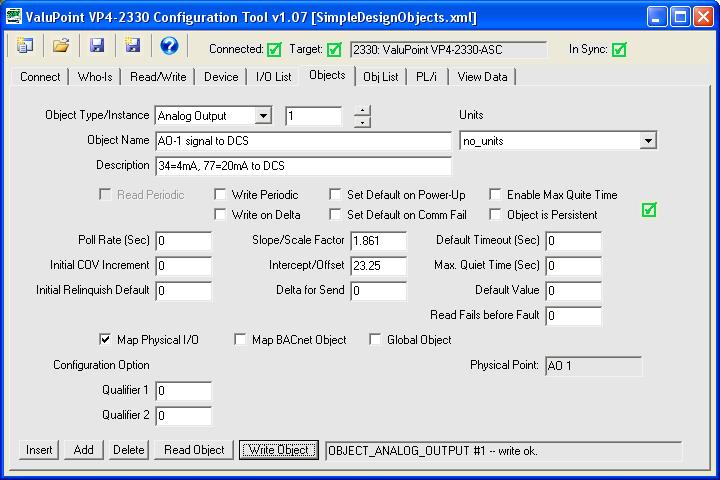
Mapping the AO object to physical hardware will be done automatically if you loaded the default configuration file, or simply read the default configuration as shipped from the device. In any event, the AO should end up looking like this:
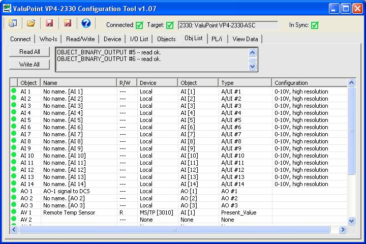
The object list in our simple test of this application now looks like this:
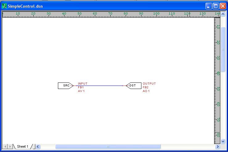
Next, use i.CanDrawIt to create a simple program to move the input value to the output object. The drawing will look like this:
Using the i.CanDrawIt tool, compile the file to create a .plx file. Then from the PL/i tab of the configuration tool, open the .plx file, and click Write to send the program to the ValuPoint. Once that is done, select Run Program from the Program Change list and click Send. The program should now be running, which you can verify by clicking the Read button. The status should appear as follows:

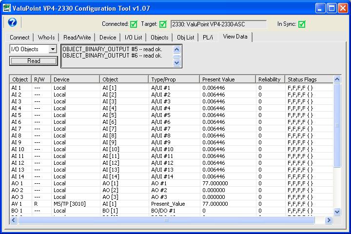
Now you should be able to read present values on the Data List page and see the value of the AV being copied to the AO.
You will see that scaling for the AO has some unusual numbers in our example. The application illustrated here called for a 4-20mA signal corresponding to a temperature reading of 34-77F. In other words, if the value in the AV object is 34, the AO should be generating 4mA. If the value in the AV object is 77, the AO should be generating 20mA.
Scaling for analog inputs uses the traditional slope-intercept formula y=mx+b. Calculation of slope would be m=(y2-y1)/(x2-x1). Once slope (m) is calculated, solve for intercept (b).
Scaling for analog outputs would theoretically be the reverse of this process, meaning subtract intercept then divide by slope. However, the implementation was coded incorrectly. The ValuPoint correctly subtracts intercept first, but multiplies by slope instead of divide. Modifying firmware would result in the same model device in the field behaving two different ways. Rather than create this dilemma, we will simply revise the calculation needed.
Calculation of slope for analog outputs still uses the standard m=(y2-y1)/(x2-x1) formula. But when solving for intercept, the formula is y=(x-b)*m.
Analog outputs produce 0-20mA given a raw value of 0-100 (with percent being implied). To generate a traditional 4-20mA signal, a non-zero value is needed to get the 4mA offset. The 4mA offset corresponds to a raw value of 20 (or 20% of 20mA). Therefore, the Y values in the slope calculation should be 100 and 20, with X values corresponding to whatever range you wish to scale to for 20mA and 4mA respectively.
In our example, the slope (m) is then (100-80)/(77-34) = 1.86. Next, solving y=(x-b)*m for b, we find that the intercept is 23.25. The scaling could have been applied on the AV object instead using the input formula for intercept. But by scaling the AO instead, we can look at the Data List and see the actual value of the AV in the range of 34 to 77.
Qualifier 1 for the analog output should be the value of the dropping resistor at the other end of the loop. If left set to 0, it will assume 500 ohms by default. If the value is anything other than 500, enter that number as the qualifier.