Splitting Bits of a Modbus Holding Register into Multiple Objects
Modbus is notorious for packing a whole bunch of things in a single holding register, especially when a collection of status bits are just one bit each. When converting those status bits to some other protocol, especially BACnet, it is user unfriendly, if not downright non-functional, to put that collection in an Analog Input object. Thankfully, Babel Buster gateways can split a single holding register full of status bits into a collection of individual Binary objects for BACnet, or just split them into multiple Modbus registers or variables for other protocols. The concept works the same for all Babel Buster gateways that talk Modbus, but we will illustrate BACnet here.
The key to splitting a packed holding register into 16 different objects is to set up rules or maps that look like you are reading the same register 16 times. Internally, the Babel Buster optimizes the query. It sees you are reading the same register over and over, and does an actual read only once and then shares the data with all 16 rules or object maps. Each time, the original Modbus data is processed according to the rule’s criteria, and the result is placed in the given target object.
Each of the read rules or object maps are set up the same as you would for reading any other unsigned 16-bit holding register. The only parameter you need to set differently is to put a non-zero value in the “mask” field. Any time the BB2-7010 (or other web enabled version of gateway) sees a non-zero mask value, it automatically treats it as a packed register. On the BB2-3010 (or other non-web gateways), you also need to check the box that says “Member of Packed Register” in the configuration tool software.
The web enabled gateways require that you place all related read (or write) rules in consecutive order in the rule list in order for all parts of the packed register to get accumulated. If the rules are not contiguous in the rule table, you will end up with multiple reads - which won’t hurt anything. But if write rules are scattered about, you will end up with multiple writes and the last write will overwrite the first writes, most likely creating results you did not intend.
The non-web gateways use a different approach to the mapping, and will go looking for other objects if an object is marked as “Member of packed register”. If the members of the packed register are not the same object type, you also need to check the box marked “Pack Mixed Object Types” so that it also searches all other object types looking for members of the same Modbus register.
When either the web or non-web gateway starts searching for members of the same register, the register type, register number, and device address must all match. Any non-match ends the search in the web gateway, or is simply skipped over in the non-web gateway.
The same masking tricks can be used to write a packed Modbus holding register. There is one additional parameter that can be useful when writing, namely the “fill” parameter. If the register contains a bit that should always be set no matter what, you use the same values that you would for mask, except put them in the “fill” window instead. Just like the “mask” is logically AND-ed with the data, the “fill” is logically OR-ed with the data before sending it out to the Modbus device.
Documentation tends to be slightly different for every Modbus device. But if your device packs multiple bits into a single holding register, the documentation will note up to 16 different items found at the same register number or address. The bits may be identified with “Bn” or “Dn” or just “bit n”. Most of the time, the least significant bit will be called bit 0 and the most significant will be bit 15. It is possible you could find reference to bit 1 through bit 16, in which case just subtract one from the number to reference the table below. For each of the 16 bit positions, the mask (or fill) will be as follows.
B0/D0/bit 0 mask = 0001
B1/D1/bit 1 mask = 0002
B2/D2/bit 2 mask = 0004
B3/D3/bit 3 mask = 0008
B4/D4/bit 4 mask = 0010
B5/D5/bit 5 mask = 0020
B6/D6/bit 6 mask = 0040
B7/D7/bit 7 mask = 0080
B8/D8/bit 8 mask = 0100
B9/D9/bit 9 mask = 0200
B10/D10/bit 10 mask = 0400
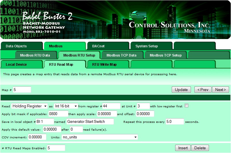
B11/D11/bit 11 mask = 0800
B12/D12/bit 12 mask = 1000
B13/D13/bit 13 mask = 2000
B14/D14/bit 14 mask = 4000
B15/D15/bit 15 mask = 8000
Some Modbus devices also back two 8-bit values into a single 16-bit register. The two values will typically be documented as “high byte” and “low byte” or simply have “H” and “L” indicated. If you run into this scenario, the masking for bytes is as follows:
High byte mask = FF00
Low byte mask = 00FF
The web page for setting up a Read Rule in the BB2-7010 is illustrated below. This screen shot happens to be for Modbus RTU, but set for Modbus TCP is very similar. When you first get to the Read Map page, it will be a tabular list of rules. To get to this page showing the expanded list of all possible configuration parameters, click on the map number in the first column of the list of rules.
The non-web gateways like BB2-3010 have configuration tool software that you can download from the product support page for the particular model of interest. There is no charge for this software, but you do need the MTX002 USB to BACnet adapter for non-web BACnet gateways.
The object map configuration page in this tool software for the BB2-3010 is illustrated below. Rather than the list of rules as found in the BB2-7010, the BB2-3010 has a map associated with each available object. Each local object in the gateway can be mapped to Modbus RTU or BACnet MS/TP in the BB2-3010. Mapping BACnet Binary Input object to a single bit found in a Modbus RTU holding register is illustrated below.
